For the best performance and durability, ensure your Global Rotomoulding tanks are installed following the specified requirements. Proper preparation is key to keeping your tank secure and functioning efficiently, even in diverse conditions.
To make the process easier, we’ve created detailed installation guides. From selecting the ideal site to reinforcing surfaces, these guides are designed to ensure a smooth and hassle-free installation.
Access the relevant product installation requirements below to guarantee precise set-up and long-lasting performance for your tank.
Rainwater Tanks
Immediate Securing of Tank
It is the purchaser’s responsibility to ensure that the tank is secured immediately following delivery, either by tying down with rope or wire, or by filling to 10% of capacity with water.
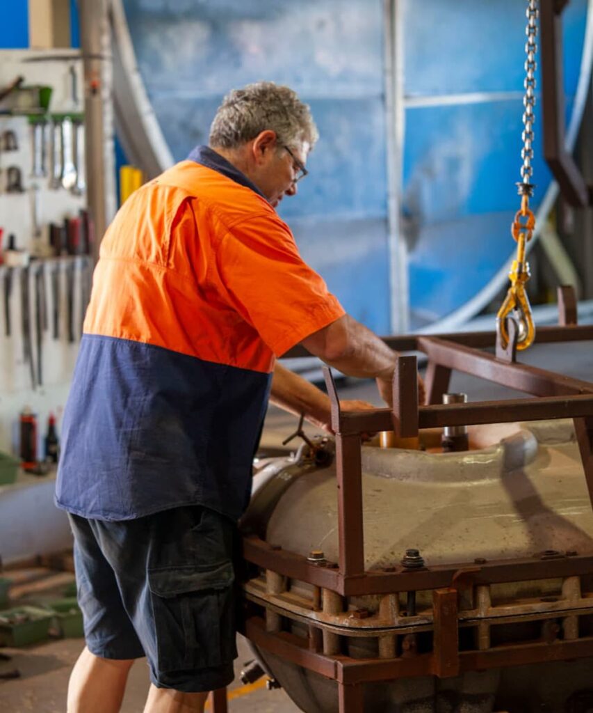
Handling and moving tanks: Move the tank by lifting, using the lifting points on the sides or top of the tank. Do not drop the tank. Do not drag the tank across rough surfaces.
Site Preparation
Global Rotomoulding or its agents do not take any responsibility for the preparation of the tank site or the installation of its products. It is the sole responsibility of the purchaser, or their agent to ensure that the site has been prepared in accordance with these instructions, and maintained on an ongoing basis. Placement of tanks must conform to local & statutory regulations.
Site Selection
Good Clean Soil (excluding Skinny Camel and Urban Camel tanks):
- Remove green cover and place tank directly on site.
- Do NOT place tank on loose soil without compacting.
Rocky Soil (excluding Skinny Camel and Urban Camel tanks):
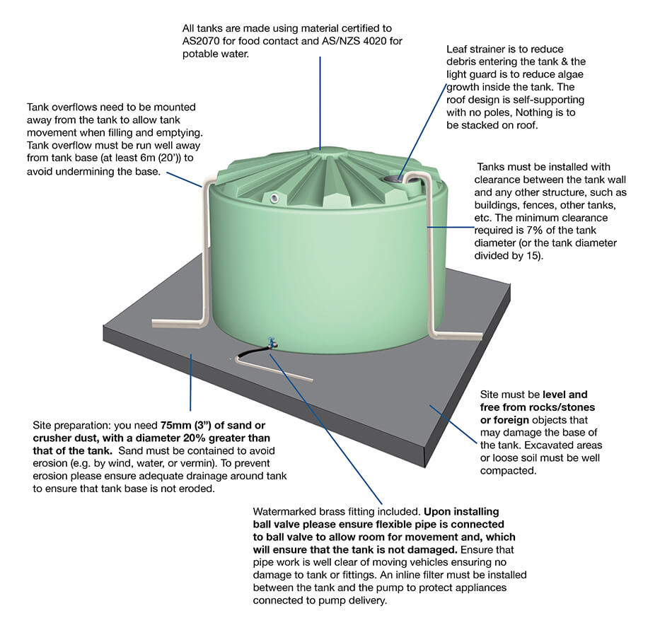
- 75mm (3”) of sand or crusher dust, with a diameter 20% greater than that of the tank.
- Sand must be contained to avoid erosion (e.g. By wind, water, or vermin).
Concrete Slab:
- Skinny Camel and Urban Camel tanks must be placed on a suitable concrete slab at least 100mm wider and longer than the tank or tank group.
- Where used, a concrete slab must be of sufficient thickness and suitably reinforced to support the weight of the tank when full.
- Surface finish must be smooth and level.
Tank Stands:
- Global Rotomoulding takes no responsibility for the suitability of tank stands.
- Bearers must have sufficient strength to prevent deflection when the tank is full.
- Use hardwood decking with a maximum gap of 12mm (1/2”) between slats, or exterior grade plywood.
- Do not use corrugated iron.
- Support inlet/outlet pipes from tank stand, and not from tank wall.
All Installations:
- Tank installation must comply with local council requirements.
- Site must be level and free from rocks/stones or foreign objects that may damage the base of the tank.
- Excavated areas or loose soil must be well compacted.
- All pipes must be well supported, and not dependant on the tank wall for stability.
- An in-line filter must be installed between the tank and the pump to protect appliances connected to pump delivery.
- Tank overflow must be run well away from tank base (at least 6m (20’)) to avoid undermining the base.
- A flexible coupling must be installed between the tank and pipe work to avoid stress on the tank wall.
- Tank must not be moved from its original installation.
- Tanks must be installed with clearance between the tank wall and any other structure, such as buildings, fences, other tanks, etc The minimum clearance required is 7% of the tank diameter (or the tank diameter divided by 15).
Please note that the Urban Camel Tanks have not been designed to support any externally applied live load to the roof of the tank. This includes using the roof of the tank for access or a surface for stacked materials and/or equipment. Non compliance with either of these requirements will void product warranty and certification.
Skinny Camel and Urban Rainwater Tanks
Immediate Securing of Tank
It is the purchaser’s responsibility to ensure that the tank is secured immediately following delivery, either by tying down with rope or wire, or by filling to 10% of capacity with water.
Handling and moving tanks: Move the tank by lifting, using the lifting points on the sides or top of the tank. Do not drop the tank. Do not drag the tank across rough surfaces.
Site Preparation
Global Rotomoulding or its agents do not take any responsibility for the preparation of the tank site or the installation of its products. It is the sole responsibility of the purchaser, or their agent to ensure that the site has been prepared in accordance with these instructions, and maintained on an ongoing basis. Placement of tanks must conform to local & statutory regulations.
Site Selection
Concrete Slab:
- Skinny Camel and Urban Camel tanks must be placed on a suitable concrete slab at least 100mm wider and longer than the tank or tank group.
- Where used, a concrete slab must be of sufficient thickness and suitably reinforced to support the weight of the tank when full.
- Surface finish must be smooth and level.
Tank Stands:
- Global Rotomoulding takes no responsibility for the suitability of tank stands.
- Bearers must have sufficient strength to prevent deflection when the tank is full.
- Use hardwood decking with a maximum gap of 12mm (1/2”) between slats, or exterior grade plywood.
- Do not use corrugated iron.
- Support inlet/outlet pipes from tank stand, and not from tank wall.
All Installations:
- Tank installation must comply with local council requirements.
- Site must be level and free from rocks/stones or foreign objects that may damage the base of the tank.
- Excavated areas or loose soil must be well compacted.
- All pipes must be well supported, and not dependant on the tank wall for stability.
- An in-line filter must be installed between the tank and the pump to protect appliances connected to pump delivery.
- Tank overflow must be run well away from tank base (at least 6m (20’)) to avoid undermining the base.
- A flexible coupling must be installed between the tank and pipe work to avoid stress on the tank wall.
- Tank must not be moved from its original installation.
- Tanks must be installed with clearance between the tank wall and any other structure, such as buildings, fences, other tanks, etc The minimum clearance required is 7% of the tank diameter (or the tank diameter divided by 15).
Please note that the Urban Camel Tanks have not been designed to support any externally applied live load to the roof of the tank. This includes using the roof of the tank for access or a surface for stacked materials and/or equipment. Non compliance with either of these requirements will void product warranty and certification.
Cartage Tanks
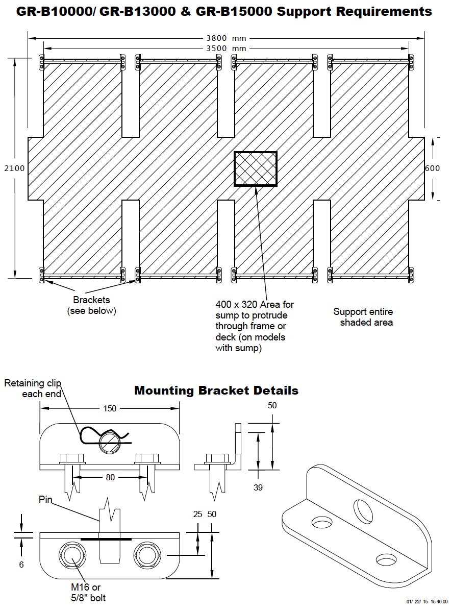
Support requirements for 10,000L, 13,000L & 15,000L cartage tanks
- 10,000 Lt, 13,000 Lt & 15,000 Lt Tanks are required to be fully supported under each foot. The centre must also be supported for the full length of the tank.
- Please refer to the mounting diagram overleaf for minimum support area.
- In addition to the above, the structure that the tank is mounted to must be sufficiently resistant to twisting, so as to prevent the tank from twisting. The amount of twisting force will vary between different installations, so it is important that the structure be strong enough to prevent twisting in that particular installation.
- Global recommend the installation of baffles in all transportable tanks greater than 2000 Litres to assist in reducing the water movement while braking and turning. Failing to use baffle bones in these tanks will void warranty claims.
Mounting requirements
- Pin Mounted tanks are to be mounted as follows: 19mm pins are inserted horizontally through holes provided in the feet.
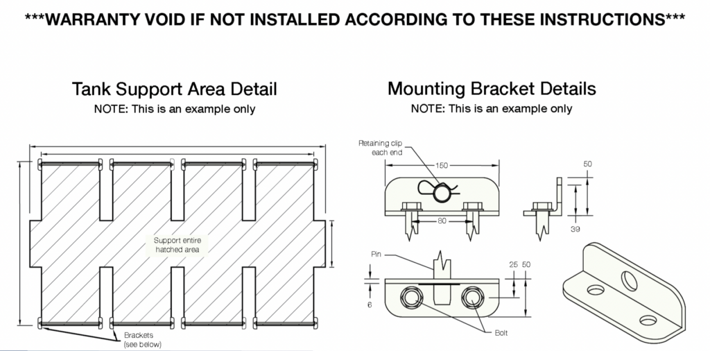
- Pins are retained using a mounting bracket which is bolted to the chassis or deck to which the tank is to be mounted. See overleaf.
- The bracket is designed to pull the pin down as the bolts are tightened, holding the tank firmly against the chassis or deck. Thus, the size and position of the hole for the pin is very important.
- The retaining clips are required as a safety feature to prevent the pins coming out if the brackets if they work loose.
- Please note that all polyethylene products are subject to natural variations in size. DO NOT simply mount the brackets using the measurements on the drawing Make adjustments to accommodate the exact size of your tank.
- We recommend using high tensile M20 or 3/4″ bolts to secure the brackets to the chassis or
- The chassis or deck must be suitable to bolt the mounting brackets to. For example, simply bolting the brackets to a 3mm checkerplate deck is not
- See illustration at right. Pin mounting allows for natural expansion and contraction of the tank.
- Load straps alone are not sufficient to restrain these.
- Minimum mounting hardware requirements (not supplied):
- 4 x 19mm pins at least 450mm long, chamfered both ends
- 8 x mounting brackets per diagram overleaf
- 16 x M20 or 3/4″ bolts, with length suited to your mounting situation
- 8 x retaining clips for 30mm pins
T-bolts
- The T-bolts holding the feet to the tank must be re-tightened when the tank is full of water. Tighten to approximately 50nm.
- Periodically check the T-bolts for tightness during the life of the tank. Re-tighten if necessary.
Connections
- Connections from the tank to any pump or pipe must be made using at least 300mm of flexible tubing.
Notes
- Global Rotomoulding or it’s agents do not take any responsibility for the preparation of the tank mount or the installation of it’s products. It is the sole responsibility of the purchaser, or their agent to ensure that the product is installed in accordance with these instructions, and maintained on an ongoing basis.
Specifications
- Dimensions given are approximate only; natural variations in shrinkage can vary some dimensions by ±1%, depending on the size and shape of the tank.
- In the interests of continually improving our products, we reserve the right to change specifications on our products without notice.
Low Profile Cartage Tanks
Support requirements for 200L and 300L low profile tanks
- 200 & 300 Lt Low Profile Tanks are required to be fully supported under each foot. The centre must also be supported for the full length of the tank.
- Please refer to the mounting diagram below for minimum support area.
- In addition to the above, the structure that the tank is mounted to must be sufficiently resistant to twisting, so as to prevent the tank from twisting. The amount of twisting force will vary between different installations, so it is important that the structure be strong enough to prevent twisting in that particular installation.
Mounting requirements
- These tanks have 4 x M12 brass threaded inserts moulded into the feet for securing them to the mounting surface.
- When selecting bolts, care must be taken to select the correct size and thread for your application. All inserts are metric treaded.
- Bolts must be long enough to go through the mounting surface and engage the threads in the brass inserts, but not so long as to ‘bottom out’ and bind in the inserts.
Connections
- Connections from the tank to any pump or pipe must be made using at least 300mm of flexible tubing.
Specifications
- Dimensions given are approximate only; natural variations in shrinkage can vary some dimensions by 1%, depending on the size and shape of the tank.
- In the interests of continually improving our products, we reserve the right to change specifications on our products without notice.
5,000L Cartage Tanks
Support requirements for 5000L cartage tank
- 5000L Tanks are required to be fully supported under each foot. The centre must also be supported for the full length of the tank.
- Please refer to the mounting diagram overleaf for minimum support area.
- In addition to the above, the structure that the tank is mounted to must be sufficiently resistant to twisting, so as to prevent the tank from twisting. The amount of twisting force will vary between different installations, so it is important that the structure be strong enough to prevent twisting in that particular installation.
- Global recommend the installation of baffles in all transportable tanks greater than 2000 Litres to assist in reducing the water movement while braking and turning. Failing to use baffle bones in these tanks will void warranty claims.
Mounting requirements
- Pin Mounted tanks are to be mounted as follows: 22mm pins are inserted horizontally through holes provided in the feet.
- Pins are retained using a mounting bracket which is bolted to the chassis or deck to which the tank is to be mounted. See overleaf.
- The bracket is designed to pull the pin down as the bolts are tightened, holding the tank firmly against the chassis or deck. Thus, the size and position of the hole for the pin is very important.
- The retaining clips are required as a safety feature to prevent the pins coming out if the brackets if they work loose.
- Please note that all polyethylene products are subject to natural variations in size. DO NOT simply mount the brackets using the measurements on the drawing Make adjustments to accommodate the exact size of your tank.
- We recommend using high tensile M16 or 5/8″ bolts to secure the brackets to the chassis or
- The chassis or deck must be suitable to bolt the mounting brackets to. For example, simply bolting the brackets to a 3mm checkerplate deck is not.
- See illustration at right. Pin mounting allows for natural expansion and contraction of the tank.
- Load straps alone are not sufficient to restrain these.
- Minimum mounting hardware requirements (not supplied):
- 6 x 22mm pins 800mm long, chamfered both ends
- 12 x mounting brackets per diagram overleaf
- 24 x M16 or 5/8″ bolts, with length suited to your mounting situation
T-bolts
- The T-bolts holding the feet to the tank must be re-tightened when the tank is full of water. Tighten to approximately 50nm.
- Periodically check the T-bolts for tightness during the life of the tank. Re-tighten if necessary.
Connections
- Connections from the tank to any pump or pipe must be made using at least 300mm of flexible tubing.
Notes
- Global Rotomoulding or it’s agents do not take any responsibility for the preparation of the tank mount or the installation of it’s products. It is the sole responsibility of the purchaser, or their agent to ensure that the product is installed in accordance with these instructions, and maintained on an ongoing basis.
Specifications
- Dimensions given are approximate only; natural variations in shrinkage can vary some dimensions by ±1%, depending on the size and shape of the tank.
- In the interests of continually improving our products, we reserve the right to change specifications on our products without notice.

10,000L Cartage Tanks
Support requirements for 10,000L cartage tank
- 10,000L Tanks are required to be fully supported under each foot. The centre must also be supported for the full length of the tank.
- Please refer to the mounting diagram overleaf for minimum support area.
- In addition to the above, the structure that the tank is mounted to must be sufficiently resistant to twisting, so as to prevent the tank from twisting. The amount of twisting force will vary between different installations, so it is important that the structure be strong enough to prevent twisting in that particular installation.
- Global recommend the installation of baffles in all transportable tanks greater than 2000 Litres to assist in reducing the water movement while braking and turning. Failing to use baffle bones in these tanks will void warranty claims.
Mounting requirements
- Pin Mounted tanks are to be mounted as follows: 30mm pins are inserted horizontally through holes provided in the feet.
- Pins are retained using a mounting bracket which is bolted to the chassis or deck to which the tank is to be mounted. See overleaf.
- The bracket is designed to pull the pin down as the bolts are tightened, holding the tank firmly against the chassis or deck. Thus, the size and position of the hole for the pin is very important.
- The retaining clips are required as a safety feature to prevent the pins coming out if the brackets if they work loose.
- Please note that all polyethylene products are subject to natural variations in size. DO NOT simply mount the brackets using the measurements on the drawing Make adjustments to accommodate the exact size of your tank.
- We recommend using high tensile M20 or 3/4″ bolts to secure the brackets to the chassis or
- The chassis or deck must be suitable to bolt the mounting brackets to. For example, simply bolting the brackets to a 3mm checkerplate deck is not.
- See illustration at right. Pin mounting allows for natural expansion and contraction of the tank.
- Load straps alone are not sufficient to restrain these
- Minimum mounting hardware requirements (not supplied):
- 4 x 30mm pins at least 450mm long, chamfered both ends
- 8 x mounting brackets per diagram overleaf
- 16 x M20 or 3/4″ bolts, with length suited to your mounting situation
- 8 x retaining clips for 30mm pins
Connections
- Connections from the tank to any pump or pipe must be made using at least 300mm of flexible tubing.
Notes
- Global Rotomoulding or it’s agents do not take any responsibility for the preparation of the tank mount or the installation of it’s products. It is the sole responsibility of the purchaser, or their agent to ensure that the product is installed in accordance with these instructions, and maintained on an ongoing basis.
Specifications
- Dimensions given are approximate only; natural variations in shrinkage can vary some dimensionss by ±40mm (depending on the size and shape of the tank).
- In the interests of continually improving our products, we reserve the right to change specifications on our products without notice.
2,000L Cartage Tanks
Support requirements for 2,000L cartage tank
- 2,000L Tanks are required to be fully supported under each foot. The centre must also be supported for the full length of the tank.
- Please refer to the mounting diagram overleaf for minimum support area.
- In addition to the above, the structure that the tank is mounted to must be sufficiently resistant to twisting, so as to prevent the tank from twisting. The amount of twisting force will vary between different installations, so it is important that the structure be strong enough to prevent twisting in that particular installation.
- Global recommend the installation of baffles in all transportable tanks greater than 2000 Litres to assist in reducing the water movement while braking and turning. Failing to use baffle bones in these tanks will void warranty claims.
Mounting requirements
- Pin Mounted tanks are to be mounted as follows: 22mm pins are inserted horizontally through holes provided in the feet.
- Pins are retained using a mounting bracket which is bolted to the chassis or deck to which the tank is to be mounted. See overleaf.
- The bracket is designed to pull the pin down as the bolts are tightened, holding the tank firmly against the chassis or deck. Thus, the size and position of the hole for the pin is very important.
- The retaining clips are required as a safety feature to prevent the pins coming out if the brackets if they work loose.
- Please note that all polyethylene products are subject to natural variations in size. DO NOT simply mount the brackets using the measurements on the drawing Make adjustments to accommodate the exact size of your tank.
- We recommend using high tensile M16 or 5/8″ bolts to secure the brackets to the chassis or
- The chassis or deck must be suitable to bolt the mounting brackets to. For example, simply bolting the brackets to a 3mm checkerplate deck is not
- See illustration at right. Pin mounting allows for natural expansion and contraction of the tank.
- Load straps alone are not sufficient to restrain these
- Minimum mounting hardware requirements (not supplied):
- 4 x 22mm pins 300mm long, chamfered both ends
- 8 x mounting brackets per diagram overleaf
- 16 x M16 or 5/8″ bolts, with length suited to your mounting situation
Connections
- Connections from the tank to any pump or pipe must be made using at least 300mm of flexible tubing.
Notes
- Global Rotomoulding or it’s agents do not take any responsibility for the preparation of the tank mount or the installation of it’s products. It is the sole responsibility of the purchaser, or their agent to ensure that the product is installed in accordance with these instructions, and maintained on an ongoing basis.
Specifications
- Dimensions given are approximate only; natural variations in shrinkage can vary some dimensions by ±1%, depending on the size and shape of the tank.
- In the interests of continually improving our products, we reserve the right to change specifications on our products without notice.

1,200L & 1,500L Cartage Tanks
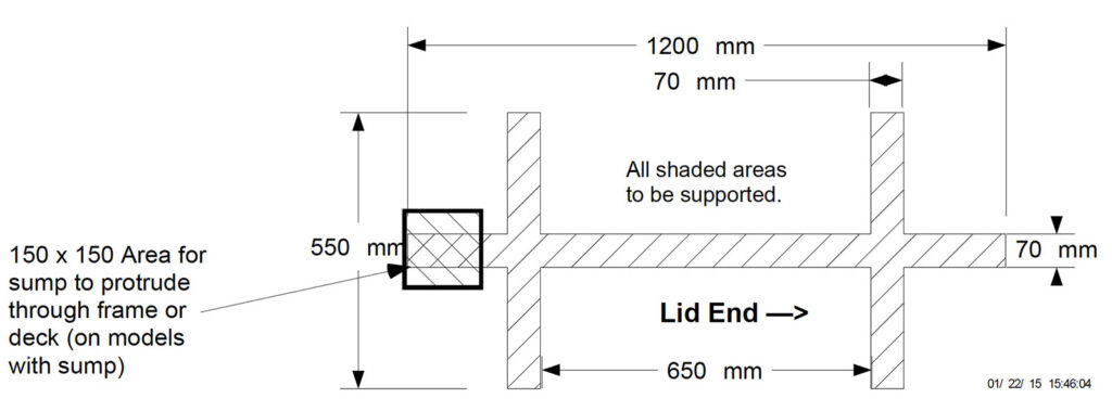
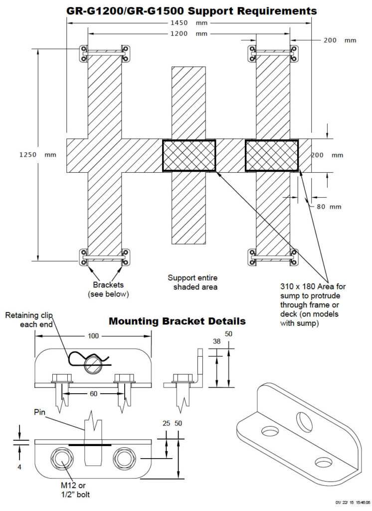
Support requirements for 1200L & 1500L cartage tanks
- 1200L & 1500L Tanks are required to be fully supported under each foot. The centre must also be supported for the full length of the tank.
- Please refer to the mounting diagram overleaf for minimum support area.
- In addition to the above, the structure that the tank is mounted to must be sufficiently resistant to twisting, so as to prevent the tank from twisting. The amount of twisting force will vary between different installations, so it is important that the structure be strong enough to prevent twisting in that particular installation.
Mounting requirements
- Pin Mounted tanks are to be mounted as follows: 19mm pins are inserted horizontally through holes provided in the feet.
- Pins are retained using a mounting bracket which is bolted to the chassis or deck to which the tank is to be mounted. See overleaf.
- The bracket is designed to pull the pin down as the bolts are tightened, holding the tank firmly against the chassis or deck. Thus, the size and position of the hole for the pin is very important.
- The retaining clips are required as a safety feature to prevent the pins coming out if the brackets if they work loose.
- Please note that all polyethylene products are subject to natural variations in size. DO NOT simply mount the brackets using the measurements on the drawing. Make adjustments to accommodate the exact size of your tank.
- We recommend using high tensile M12 or 1/2″ bolts to secure the brackets to the chassis or
- The chassis or deck must be suitable to bolt the mounting brackets to. For example, simply bolting the brackets to a 3mm checkerplate deck is not
- See illustration at right. Pin mounting allows for natural expansion and contraction of the tank.
- Load straps alone are not sufficient to restrain these
- Minimum mounting hardware requirements (not supplied):
- 4 x 19mm pins 250mm long, chamfered both ends
- 8 x mounting brackets per diagram overleaf
- 16 x M12 or 1/2″ bolts, with length suited to your mounting situation
Connections
- Connections from the tank to any pump or pipe must be made using at least 300mm of flexible tubing.
Notes
- Global Rotomoulding or it’s agents do not take any responsibility for the preparation of the tank mount or the installation of it’s products. It is the sole responsibility of the purchaser, or their agent to ensure that the product is installed in accordance with these instructions, and maintained on an ongoing basis.
Specifications
- Dimensions given are approximate only; natural variations in shrinkage can vary some dimensions by ±1%, depending on the size and shape of the tank.
- In the interests of continually improving our products, we reserve the right to change specifications on our products without notice.
Cartage / Spray Tanks
Support requirements
- All tanks are required to be fully supported under each foot and centre (For the full length of the tank)
- Please refer to the mounting diagram overleaf for minimum support area.
- In addition to the above, the structure that the tank is mounted to must be sufficiently resistant to twisting, so as to prevent the tank from twisting. The amount of twisting force will vary between different installations, so it is important that the structure be strong enough to prevent twisting in that particular installation.
- Global recommend the installation of baffles in all transportable tanks greater than 2000 Litres to assist in reducing the water movement while braking and turning. Failing to use baffle bones in these tanks will void warranty claims.
Mounting requirements
- Pin Mounted tanks are to be mounted as follows: Pins are inserted horizontally through holes provided in the feet.
- Pins are retained using a mounting bracket which is bolted to the chassis or deck to which the tank is to be mounted. See below.
- The bracket is designed to pull the pin down as the bolts are tightened, holding the tank firmly against the chassis or deck. Thus, the size and position of the hole for the pin is very important.
- The retaining clips are required as a safety feature to prevent the pins coming out of the brackets
- Please note that all polyethylene products are subject to natural variations in size. DO NOT simply mount the brackets using the measurements on the drawing below. Make adjustments to accommodate the exact size of your tank.
- We recommend using high tensile bolts to secure the brackets to the chassis or deck.
The chassis or deck must be suitable to bolt the mounting brackets to. For example, simply bolting the brackets to a 3mm checker plate deck is not sufficient. - Pin mounting allows for natural expansion and contraction of the tank.
- Load straps alone are not sufficient to restrain these tanks.
- Mounting hardware is not supplied with your tank. See your specific tank installation requirements for that tanks individual information.
Connections
- Connections at tank outlet MUST have at least 300mm of flexible tubing/ hose before any ridged metal connections to pump or pipe.
Notes
- Global Rotomoulding or it’s agents do not take any responsibility for the preparation of the tank mount or the installation of it’s products. It is the sole responsibility of the purchaser, or their agent to ensure that the product is installed in accordance with these instructions, and maintained on an ongoing basis.
Specifications
- Dimensions given are approximate only; natural variations in shrinkage can vary some dimensions by ±40mm (depending on the size and shape of the tank.)
- In the interests of continually improving our products, we reserve the right to change specifications on our products without notice.
2,000L Diesel Cartage Tanks
Support requirements for 2,000L diesel cartage tank
- 2000 Lt Tanks are required to be fully supported under each foot. The centre must also be supported for the full length of the tank.
- Please refer to the mounting diagram overleaf for minimum support area.
- In addition to the above, the structure that the tank is mounted to must be sufficiently resistant to twisting, so as to prevent the tank from twisting. The amount of twisting force will vary between different installations, so it is important that the structure be strong enough to prevent twisting in that particular installation.
- Global recommend the installation of baffles in all transportable tanks greater than 2000 Litres to assist in reducing the water movement while braking and turning. Failing to use baffle bones in these tanks will void warranty claims.
Mounting requirements
- Pin Mounted tanks are to be mounted as follows: 22mm pins are inserted horizontally through holes provided in the feet.
- Pins are retained using a mounting bracket which is bolted to the chassis or deck to which the tank is to be mounted. See overleaf.
- The bracket is designed to pull the pin down as the bolts are tightened, holding the tank firmly against the chassis or deck. Thus, the size and position of the hole for the pin is very important.
- The retaining clips are required as a safety feature to prevent the pins coming out if the brackets if they work loose.
- Please note that all polyethylene products are subject to natural variations in size. DO NOT simply mount the brackets using the measurements on the drawing Make adjustments to accommodate the exact size of your tank.
- We recommend using high tensile M16 or 5/8″ bolts to secure the brackets to the chassis or
- The chassis or deck must be suitable to bolt the mounting brackets to. For example, simply bolting the brackets to a 3mm checkerplate deck is not
- See illustration at right. Pin mounting allows for natural expansion and contraction of the tank.
- Load straps alone are not sufficient to restrain these
- Minimum mounting hardware requirements (not supplied):
- 6 x 22mm pins 800mm long, chamfered both ends
- 12 x mounting brackets per diagram overleaf
- 24 x M16 or 5/8″ bolts, with length suited to your mounting situation
T-bolts
- The T-bolts holding the feet to the tank must be re-tightened when the tank is full of water. Tighten to approximately 50nm.
- Periodically check the T-bolts for tightness during the life of the tank. Re-tighten if necessary.
Connections
- Connections from the tank to any pump or pipe must be made using at least 300mm of flexible tubing.
Notes
- Global Rotomoulding or it’s agents do not take any responsibility for the preparation of the tank mount or the installation of it’s products. It is the sole responsibility of the purchaser, or their agent to ensure that the product is installed in accordance with these instructions, and maintained on an ongoing basis.
Specifications
- Dimensions given are approximate only; natural variations in shrinkage can vary some dimensions by ±1%, depending on the size and shape of the tank.
- In the interests of continually improving our products, we reserve the right to change specifications on our products without notice.
4,000L Cartage Tanks
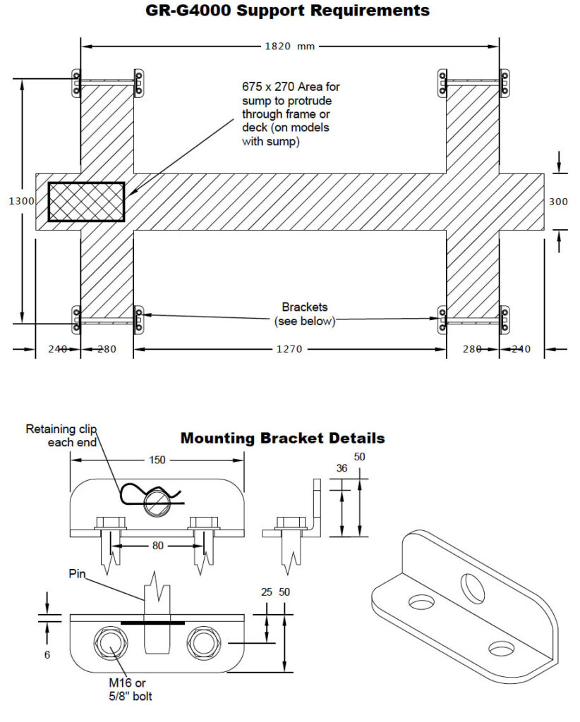
Support requirements for 4,000L cartage tank
- 4,000L Tanks are required to be fully supported under each foot. The centre must also be supported for the full length of the tank.
- Please refer to the mounting diagram overleaf for minimum support area.
- In addition to the above, the structure that the tank is mounted to must be sufficiently resistant to twisting, so as to prevent the tank from twisting. The amount of twisting force will vary between different installations, so it is important that the structure be strong enough to prevent twisting in that particular installation.
- Global recommend the installation of baffles in all transportable tanks greater than 2000 Litres to assist in reducing the water movement while braking and turning. Failing to use baffle bones in these tanks will void warranty claims.
Mounting requirements
- Pin Mounted tanks are to be mounted as follows: 22mm pins are inserted horizontally through holes provided in the feet.
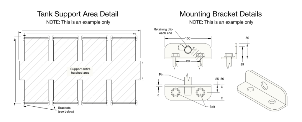
- Pins are retained using a mounting bracket which is bolted to the chassis or deck to which the tank is to be mounted. See overleaf.
- The bracket is designed to pull the pin down as the bolts are tightened, holding the tank firmly against the chassis or deck. Thus, the size and position of the hole for the pin is very important.
- The retaining clips are required as a safety feature to prevent the pins coming out if the brackets if they work loose.
- Please note that all polyethylene products are subject to natural variations in size. DO NOT simply mount the brackets using the measurements on the drawing. Make adjustments to accommodate the exact size of your tank.
- We recommend using high tensile M16 or 5/8″ bolts to secure the brackets to the chassis or
- The chassis or deck must be suitable to bolt the mounting brackets to. For example, simply bolting the brackets to a 3mm checkerplate deck is not
- See illustration at right. Pin mounting allows for natural expansion and contraction of the tank.
- Load straps alone are not sufficient to restrain these
- Minimum mounting hardware requirements (not supplied):
- 4 x 22mm pins 300mm long, chamfered both ends
- 8 x mounting brackets per diagram overleaf
- 16 x M16 or 5/8″ bolts, with length suited to your mounting situation
Connections
- Connections from the tank to any pump or pipe must be made using at least 300mm of flexible tubing.
Notes
- Global Rotomoulding or it’s agents do not take any responsibility for the preparation of the tank mount or the installation of it’s products. It is the sole responsibility of the purchaser, or their agent to ensure that the product is installed in accordance with these instructions, and maintained on an ongoing basis.
Specifications
- Dimensions given are approximate only; natural variations in shrinkage can vary some dimensions by ±1%, depending on the size and shape of the tank.
- In the interests of continually improving our products, we reserve the right to change specifications on our products without notice.
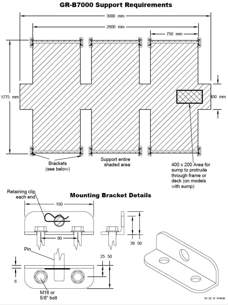
7,000L Cartage Tanks
Support requirements for 7,000L cartage tank
- 7,000L Tanks are required to be fully supported under each foot. The centre must also be supported for the full length of the tank.
- Please refer to the mounting diagram overleaf for minimum support area.
- In addition to the above, the structure that the tank is mounted to must be sufficiently resistant to twisting, so as to prevent the tank from twisting. The amount of twisting force will vary between different installations, so it is important that the structure be strong enough to prevent twisting in that particular installation.
- Global recommend the installation of baffles in all transportable tanks greater than 2000 Litres to assist in reducing the water movement while braking and turning. Failing to use baffle bones in these tanks will void warranty claims.
Mounting requirements
- Pin Mounted tanks are to be mounted as follows: 22mm pins are inserted horizontally through holes provided in the feet.
- Pins are retained using a mounting bracket which is bolted to the chassis or deck to which the tank is to be mounted. See overleaf.
- The bracket is designed to pull the pin down as the bolts are tightened, holding the tank firmly against the chassis or deck. Thus, the size and position of the hole for the pin is very important.
- The retaining clips are required as a safety feature to prevent the pins coming out if the brackets if they work loose.
- Please note that all polyethylene products are subject to natural variations in size. DO NOT simply mount the brackets using the measurements on the drawing. Make adjustments to accommodate the exact size of your tank.
- We recommend using high tensile M16 or 5/8″ bolts to secure the brackets to the chassis or
- The chassis or deck must be suitable to bolt the mounting brackets to. For example, simply bolting the brackets to a 3mm checkerplate deck is not
- See illustration at right. Pin mounting allows for natural expansion and contraction of the tank.
- Load straps alone are not sufficient to restrain these
- Minimum mounting hardware requirements (not supplied):
- 6 x 22mm pins 800mm long, chamfered both ends
- 12 x mounting brackets per diagram overleaf
- 24 x M16 or 5/8″ bolts, with length suited to your mounting situation
T-bolts
- The T-bolts holding the feet to the tank must be re-tightened when the tank is full of water. Tighten to approximately 50nm.
- Periodically check the T-bolts for tightness during the life of the tank. Re-tighten if necessary.
Connections
- Connections from the tank to any pump or pipe must be made using at least 300mm of flexible tubing.
Notes
- Global Rotomoulding or it’s agents do not take any responsibility for the preparation of the tank mount or the installation of it’s products. It is the sole responsibility of the purchaser, or their agent to ensure that the product is installed in accordance with these instructions, and maintained on an ongoing basis.
Specifications
- Dimensions given are approximate only; natural variations in shrinkage can vary some dimensions by ±1%, depending on the size and shape of the tank.
- In the interests of continually improving our products, we reserve the right to change specifications on our products without notice.
400L & 600L Cartage Tanks
Support requirements for 400L & 600L cartage tanks
- 400 & 600 Lt Tanks are required to be fully supported under each foot. The centre must also be supported for the full length of the tank.
- Please refer to the mounting diagram overleaf for minimum support area.
- In addition to the above, the structure that the tank is mounted to must be sufficiently resistant to twisting, so as to prevent the tank from twisting. The amount of twisting force will vary between different installations, so it is important that the structure be strong enough to prevent twisting in that particular installation.
Mounting requirements
- in Mounted tanks are to be mounted as follows: 16mm pins are inserted horizontally through holes provided in the feet.
- Pins are retained using a mounting bracket which is bolted to the chassis or deck to which the tank is to be mounted. See overleaf.
- The bracket is designed to pull the pin down as the bolts are tightened, holding the tank firmly against the chassis or deck. Thus, the size and position of the hole for the pin is very important.
- The retaining clips are required as a safety feature to prevent the pins coming out if the brackets if they work loose.
- Please note that all polyethylene products are subject to natural variations in size. DO NOT simply mount the brackets using the measurements on the drawing Make adjustments to accom- modate the exact size of your tank.
- We recommend using high tensile M12 or 1/2″ bolts to secure the brackets to the chassis or
- The chassis or deck must be suitable to bolt the mounting brackets to. For example, simply bolting the brackets to a 3mm checkerplate deck is not
- See illustration at right. Pin mounting allows for natural expansion and contraction of the tank.
- Load straps alone are not sufficient to restrain these
- Minimum mounting hardware requirements (not supplied):
- 4 x 16mm pins 130mm long, chamfered both ends
- 8 x mounting brackets per diagram overleaf
- 16 x M12 or 1/2″ bolts, with length suited to your mounting situation
Connections
- Connections from the tank to any pump or pipe must be made using at least 300mm of flexible tubing.
Notes
- Global Rotomoulding or it’s agents do not take any responsibility for the preparation of the tank mount or the installation of it’s products. It is the sole responsibility of the purchaser, or their agent to ensure that the product is installed in accordance with these instructions, and maintained on an ongoing basis.
Specifications
- Dimensions given are approximate only; natural variations in shrinkage can vary some dimensions by ±1%, depending on the size and shape of the tank.
- In the interests of continually improving our products, we reserve the right to change specifications on our products without notice.

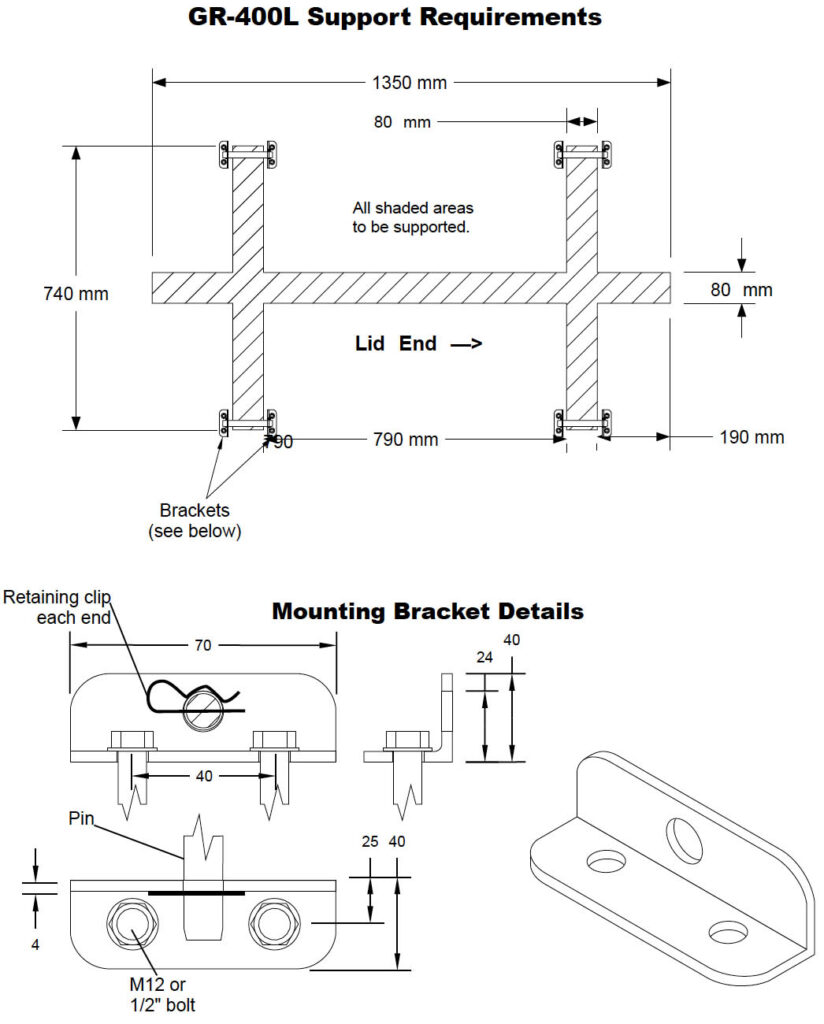
400L Low Profile Tanks
Support requirements for 400L low profile tanks
- 400L Low Profile Tanks are required to be fully supported under each foot. The centre must also be supported for the full length of the tank.
- Please refer to the mounting diagram overleaf for minimum support area.
- In addition to the above, the structure that the tank is mounted to must be sufficiently resistant to twisting, so as to prevent the tank from twisting. The amount of twisting force will vary between different installations, so it is important that the structure be strong enough to prevent twisting in that particular installation.
Mounting requirements
- Pin Mounted tanks are to be mounted as follows: 16mm pins are inserted horizontally through holes provided in the feet.
- Pins are retained using a mounting bracket which is bolted to the chassis or deck to which the tank is to be mounted. See overleaf.
- The bracket is designed to pull the pin down as the bolts are tightened, holding the tank firmly against the chassis or deck. Thus, the size and position of the hole for the pin is very important.
- The retaining clips are required as a safety feature to prevent the pins coming out if the brackets if they work loose.
- Please note that all polyethylene products are subject to natural variations in size. DO NOT simply mount the brackets using the measurements on the drawing Make adjustments to accom- modate the exact size of your tank.
- We recommend using high tensile M12 or 1/2″ bolts to secure the brackets to the chassis or
- The chassis or deck must be suitable to bolt the mounting brackets to. For example, simply bolting the brackets to a 3mm checkerplate deck is not
- See illustration at right. Pin mounting allows for natural expansion and contraction of the tank.
- Load straps alone are not sufficient to restrain these
- Minimum mounting hardware requirements (not supplied):
- 4 x 16mm pins 130mm long, chamfered both ends
- 8 x mounting brackets per diagram overleaf
- 16 x M12 or 1/2″ bolts, with length suited to your mounting situation
Connections
- Connections from the tank to any pump or pipe must be made using at least 300mm of flexible tubing.
Notes
- Global Rotomoulding or it’s agents do not take any responsibility for the preparation of the tank mount or the installation of it’s products. It is the sole responsibility of the purchaser, or their agent to ensure that the product is installed in accordance with these instructions, and maintained on an ongoing basis.
Specifications
- Dimensions given are approximate only; natural variations in shrinkage can vary some dimensions by ±1%, depending on the size and shape of the tank.
- In the interests of continually improving our products, we reserve the right to change specifications on our products without notice.
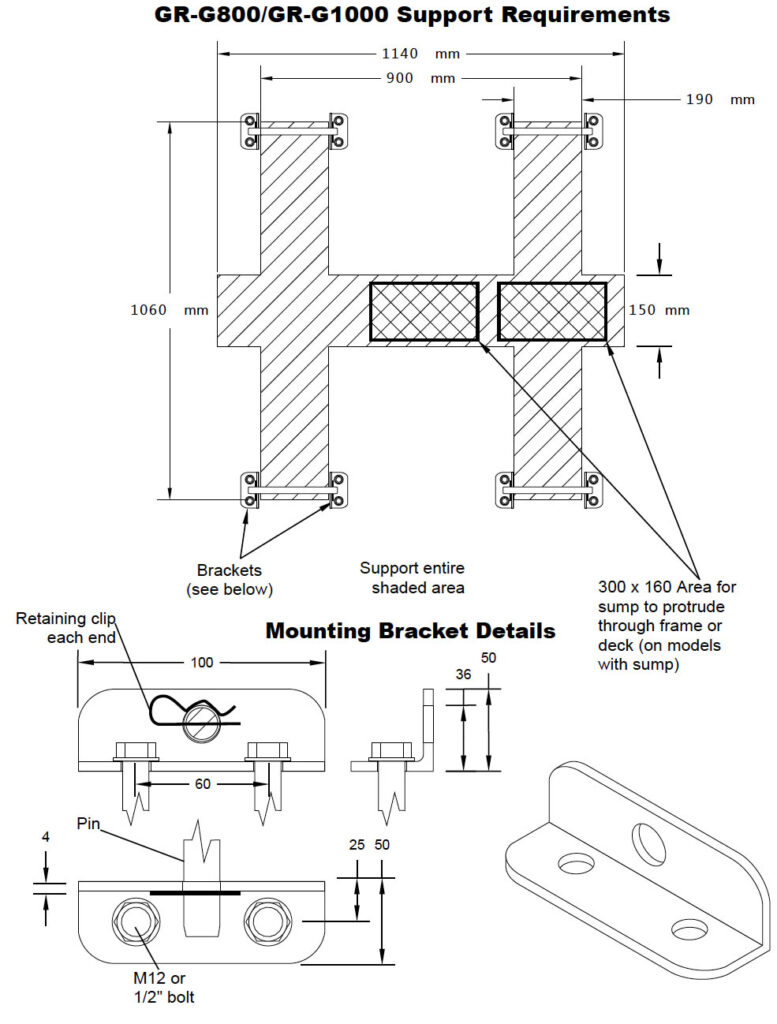
800L & 1,000L Cartage Tanks
Support requirements for 800L & 1,000L cartage tanks
- 800L & 1000L Tanks are required to be fully supported under each foot. The centre must also be supported for the full length of the tank.
- Please refer to the mounting diagram overleaf for minimum support area.
- In addition to the above, the structure that the tank is mounted to must be sufficiently resistant to twisting, so as to prevent the tank from twisting. The amount of twisting force will vary between different installations, so it is important that the structure be strong enough to prevent twisting in that particular installation.
Mounting requirements
- Pin Mounted tanks are to be mounted as follows: 19mm pins are inserted horizontally through holes provided in the feet.
- Pins are retained using a mounting bracket which is bolted to the chassis or deck to which the tank is to be mounted. See overleaf.
- The bracket is designed to pull the pin down as the bolts are tightened, holding the tank firmly against the chassis or deck. Thus, the size and position of the hole for the pin is very important.
- The retaining clips are required as a safety feature to prevent the pins coming out if the brackets if they work loose.
- Please note that all polyethylene products are subject to natural variations in size. DO NOT simply mount the brackets using the measurements on the drawing Make adjustments to accom- modate the exact size of your tank.
- We recommend using high tensile M12 or 1/2″ bolts to secure the brackets to the chassis or
- The chassis or deck must be suitable to bolt the mounting brackets to. For example, simply bolting the brackets to a 3mm checkerplate deck is not
- See illustration at right. Pin mounting allows for natural expansion and contraction of the tank.
- Load straps alone are not sufficient to restrain these
- Minimum mounting hardware requirements (not supplied):
- 4 x 19mm pins 240mm long, chamfered both ends
- 8 x mounting brackets per diagram overleaf
- 16 x M12 or 1/2″ bolts, with length suited to your mounting situation
Connections
- Connections from the tank to any pump or pipe must be made using at least 300mm of flexible tubing.
Notes
- Global Rotomoulding or it’s agents do not take any responsibility for the preparation of the tank mount or the installation of it’s products. It is the sole responsibility of the purchaser, or their agent to ensure that the product is installed in accordance with these instructions, and maintained on an ongoing basis.
Specifications
- Dimensions given are approximate only; natural variations in shrinkage can vary some dimensions by ±1%, depending on the size and shape of the tank.
- In the interests of continually improving our products, we reserve the right to change specifications on our products without notice.
Industrial Tanks
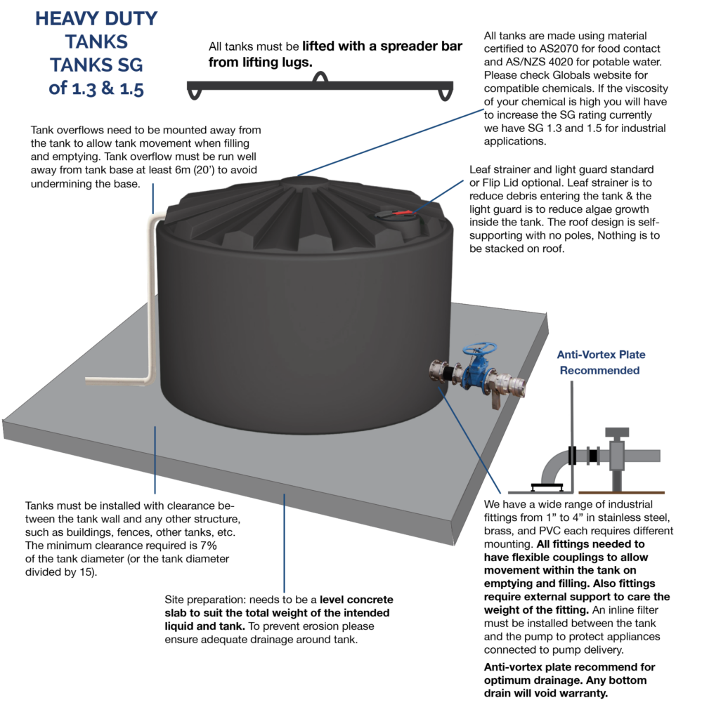
Immediate Securing of Tank:
It is the purchaser’s responsibility to ensure that the tank is secured immediately following delivery, either by tying down with rope or wire, or by filling to sufficient weight to ensure it is secure.
- Tank must not be moved from its original installation site.
- Tank installation must comply with local council requirements.
3,000L Cartage Tanks
Support requirements for 3,000L cartage tank
- 3000 Lt Tanks are required to be fully supported under each foot. The centre must also be supported for the full length of the tank.
- Please refer to the mounting diagram overleaf for minimum support area.
- In addition to the above, the structure that the tank is mounted to must be sufficiently resistant to twisting, so as to prevent the tank from twisting. The amount of twisting force will vary between different installations, so it is important that the structure be strong enough to prevent twisting in that particular installation.
- Global recommend the installation of baffles in all transportable tanks greater than 2000 Litres to assist in reducing the water movement while braking and turning. Failing to use baffle bones in these tanks will void warranty claims.
Mounting requirements
- Pin Mounted tanks are to be mounted as follows: 22mm pins are inserted horizontally through holes provided in the feet.
- Pins are retained using a mounting bracket which is bolted to the chassis or deck to which the tank is to be mounted. See overleaf.
- The bracket is designed to pull the pin down as the bolts are tightened, holding the tank firmly against the chassis or deck. Thus, the size and position of the hole for the pin is very important.
- The retaining clips are required as a safety feature to prevent the pins coming out if the brackets if they work loose.
- Please note that all polyethylene products are subject to natural variations in size. DO NOT simply mount the brackets using the measurements on the drawing Make adjustments to accom- modate the exact size of your tank.
- We recommend using high tensile M16 or 5/8″ bolts to secure the brackets to the chassis or
- The chassis or deck must be suitable to bolt the mounting brackets to. For example, simply bolting the brackets to a 3mm checkerplate deck is not
- See illustration at right. Pin mounting allows for natural expansion and contraction of the tank.
- Load straps alone are not sufficient to restrain these
- Minimum mounting hardware requirements (not supplied):
- 4 x 22mm pins 300mm long, chamfered both ends
- 8 x mounting brackets per diagram overleaf
- 16 x M16 or 5/8″ bolts, with length suited to your mounting situation
Connections
- Connections from the tank to any pump or pipe must be made using at least 300mm of flexible tubing.
Notes
- Global Rotomoulding or it’s agents do not take any responsibility for the preparation of the tank mount or the installation of it’s products. It is the sole responsibility of the purchaser, or their agent to ensure that the product is installed in accordance with these instructions, and maintained on an ongoing basis.
Specifications
- Dimensions given are approximate only; natural variations in shrinkage can vary some dimensions by ±1%, depending on the size and shape of the tank.
- In the interests of continually improving our products, we reserve the right to change specifications on our products without notice.

10,000L, 13,000L and 15,000L Cartage Tanks
Support requirements for 10,000L, 13,000L and 15,000L cartage tanks
- 10,000L,13,000L & 15,000L Tanks are required to be fully supported under each foot. The centre must also be supported for the full length of the tank.
- Please refer to the mounting diagram overleaf for minimum support area.
- In addition to the above, the structure that the tank is mounted to must be sufficiently resistant to twisting, so as to prevent the tank from twisting. The amount of twisting force will vary between different installations, so it is important that the structure be strong enough to prevent twisting in that particular installation.
- Global RotoMoulding recommend the installation of baffles in all transportable tanks greater than 2000 Litres to assist in reducing the water movement while braking and turning. Failing to use baffle bones in these tanks will void warranty claims.
Mounting requirements
- Pin Mounted tanks are to be mounted as follows: 30mm pins are inserted horizontally through holes provided in the feet.
- Pins are retained using a mounting bracket which is bolted to the chassis or deck to which the tank is to be mounted. See overleaf.
- The bracket is designed to pull the pin down as the bolts are tightened, holding the tank firmly against the chassis or deck. Thus, the size and position of the hole for the pin is very important.
- The retaining clips are required as a safety feature to prevent the pins coming out if the brackets if they work loose.
- Please note that all polyethylene products are subject to natural variations in size. DO NOT simply mount the brackets using the measurements on the drawing Make adjustments to accom- modate the exact size of your tank.
- We recommend using high tensile M20 or 3/4″ bolts to secure the brackets to the chassis or
- The chassis or deck must be suitable to bolt the mounting brackets to. For example, simply bolting the brackets to a 3mm checkerplate deck is not
- See illustration at right. Pin mounting allows for natural expansion and contraction of the tank.
- Load straps alone are not sufficient to restrain these
- Minimum mounting hardware requirements (not supplied):
- 4 x 30mm pins at least 450mm long, chamfered both ends
- 8 x mounting brackets per diagram overleaf
- 16 x M20 or 3/4″ bolts, with length suited to your mounting situation
- 8 x retaining clips for 30mm pins
T-Bolts
- The T-bolts holding the feet to the tank must be re-tightened when the tank is full of water. Tighten to approximately 50nm.Periodically check the T-bolts for tightness during the life of the tank. Re-tighten if necessary.
Connections
- Connections from the tank to any pump or pipe must be made using at least 300mm of flexible tubing.
Notes
- Global Rotomoulding or it’s agents do not take any responsibility for the preparation of the tank mount or the installation of it’s products. It is the sole responsibility of the purchaser, or their agent to ensure that the product is installed in accordance with these instructions, and maintained on an ongoing basis.
Specifications
- Dimensions given are approximate only; natural variations in shrinkage can vary some dimensions by ±1%, depending on the size and shape of the tank.
- In the interests of continually improving our products, we reserve the right to change specifications on our products without notice.

Notice
All purchasers must, on receipt of the tank, read and follow the installation requirements supplied with the tank. If your tank was supplied without installation requirements, please contact us for a copy.
Failure to comply with the installation requirements will void your warranty.