Installation Requirements for 2000ltr Diesel Cartage Tank
SUPPORT REQUIREMENTS FOR 2000LTR DIESEL CARTAGE TANK:
- 2000 Lt Tanks are required to be fully supported under each foot. The centre must also be supported for the full length of the tank.
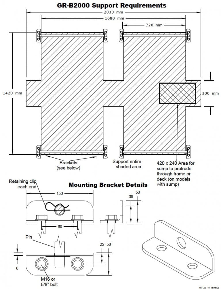
- Please refer to the mounting diagram overleaf for minimum support area.
- In addition to the above, the structure that the tank is mounted to must be sufficiently resistant to twisting, so as to prevent the tank from twisting. The amount of twisting force will vary between different installations, so it is important that the structure be strong enough to prevent twisting in that particular installation.
- Global recommend the installation of baffles in all transportable tanks greater than 2000 Litres to assist in reducing the water movement while braking and turning. Failing to use baffle bones in these tanks will void warranty claims.
MOUNTING REQUIREMENTS:
- Pin Mounted tanks are to be mounted as follows: 22mm pins are inserted horizontally through holes provided in the feet.
- Pins are retained using a mounting bracket which is bolted to the chassis or deck to which the tank is to be mounted. See overleaf.
- The bracket is designed to pull the pin down as the bolts are tightened, holding the tank firmly against the chassis or deck. Thus, the size and position of the hole for the pin is very important.
- The retaining clips are required as a safety feature to prevent the pins coming out if the brackets if they work loose.
- Please note that all polyethylene products are subject to natural variations in size. DO NOT simply mount the brackets using the measurements on the drawing Make adjustments to accommodate the exact size of your tank.
- We recommend using high tensile M16 or 5/8″ bolts to secure the brackets to the chassis or
- The chassis or deck must be suitable to bolt the mounting brackets to. For example, simply bolting the brackets to a 3mm checkerplate deck is not
- See illustration at right. Pin mounting allows for natural expansion and contraction of the tank.
- Load straps alone are not sufficient to restrain these
- Minimum mounting hardware requirements (not supplied):
- 6 x 22mm pins 800mm long, chamfered both ends
- 12 x mounting brackets per diagram overleaf
- 24 x M16 or 5/8″ bolts, with length suited to your mounting situation
T-BOLTS:
- The T-bolts holding the feet to the tank must be re-tightened when the tank is full of water. Tighten to approximately 50nm.
- Periodically check the T-bolts for tightness during the life of the tank. Re-tighten if necessary.
CONNECTIONS:
- Connections from the tank to any pump or pipe must be made using at least 300mm of flexible tubing
NOTES:
- Global Roto-Moulding or it’s agents do not take any responsibility for the preparation of the tank mount or the installation of it’s products. It is the sole responsibility of the purchaser, or their agent to ensure that the product is installed in accordance with these instructions, and maintained on an ongoing basis.
SPECIFICATIONS:
- Dimensions given are approximate only; natural variations in shrinkage can vary some dimensions by ±1%, depending on the size and shape of the tank.
- In the interests of continually improving our products, we reserve the right to change specifications on our products without notice.

